
With the increasing size of offshore structures, wind loads are becoming more and more important when designing vessels for operational conditions. For some locations, the wind may be the predominant load factor.
There are several ways to determine the wind loads of typical vessels. A dramatic growth in computing power has meant that Computational Fluid Dynamics (CFD) has become increasingly capable of calculating the wind load coefficients. This article discusses the possibilities of using CFD to determine wind loads.
Why CFD?
Using a numerical tool does not require the production of a physical model, and thus can be used early on in the design phase to assess the wind loads and in turn, optimise the design. Secondly, CFD calculations compute the wind speed, wind direction and local pressures on the hull with a high resolution of about 1 m2. This means that information about wind loads is available for every square metre of the vessel, and areas where wind loads are at their highest (cranes for instance) can be distinguished and consequently, designs can be adapted. In addition, the wind field behind the vessel can be extracted and used as input for time domain simulations of two vessels in close proximity. Lastly, CFD can be used to visualise the flow, therefore we have a better understanding of why the wind is behaving in a certain manner.
ReFRESCO
At MARIN, we use our CFD software ReFRESCO to calculate wind loads. Developed in cooperation with several universities, ReFRESCO has been tailormade for the marine industry. ReFRESCO is ideal for research purposes, where full control over the numerical settings is required. Based on these research projects, common best practice guidelines are established, which are used for industry projects.
WINDLOAD JIP
Within the WINDLOAD Joint Industry Project, a semi-submersible platform and a Floating Production Storage and Offloading (FPSO) unit have been tested in three different wind tunnel facilities and CFD computations were performed by different companies. The results obtained by the CFD benchmark participants[1] have been published. The comparison showed that the scatter between the different CFD results is comparable to the scatter between the wind tunnel tests. Generally, CFD tends to give loads that are a few percent lower, which is most likely due to a slightly lower wind velocity at the target location compared to the wind tunnel tests. The lower velocity in the CFD calculations is due to numerical diffusion, which reduces the wind speed by around 1%.
A snapshot of a result is shown in Figure 1. The colours are used to indicate the pressure coefficient, with red indicating a high pressure and blue a low pressure region. Furthermore, regions with high vorticity (rotation of air) are shown as isosurfaces. From video material, regions are visible where vortices are shed from the turret and helideck, which result in unsteady wind flow behind these structures.
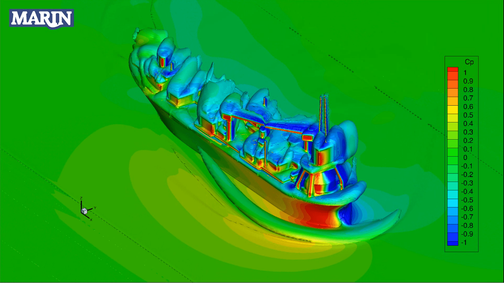
Figure 1: Airflow around the Wind Load JIP generic FPSO
Side-by-side and tandem offloading configurations
In addition to single vessels, CFD is used to establish coefficients for side-by-side and tandem offloading configurations. One example is shown in Figure 2 for a simplified FPSO and a shuttle tanker[2]. Coefficients for the shuttle tanker match the experiments well, for both the shielded and unshielded configurations.
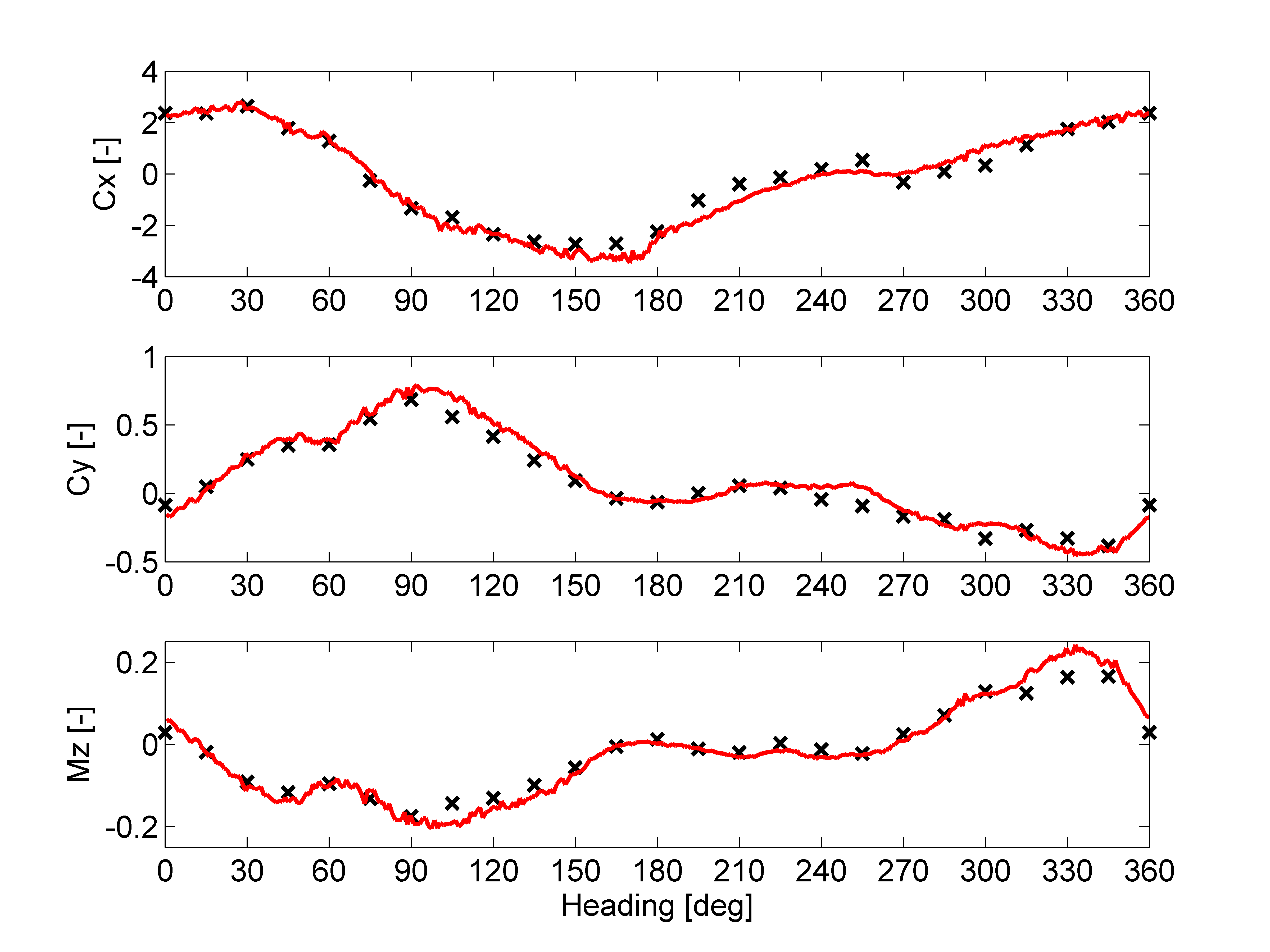
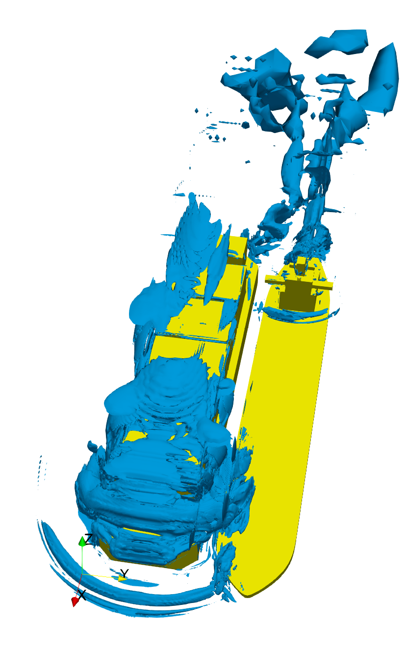
Figure 2: Side-by-side configuration with vorticity iso-surface (left) and comparison between CFD (black crosses) to wind tunnel (red) for the shuttle tanker (right)
Increasingly complex calculations
At the moment, CFD is capable of computing wind load coefficients with a similar level of accuracy as wind tunnel tests. With the increase in computational power, such calculations will become faster and easier. As a result, CFD calculations are being conducted more often for a wide range of vessel types. The growth in computational power also allows for the increasing complexity of the calculations. Instead of simplified vessels, more complex topside configurations are now taken into account and multiple vessels in close proximity. Meanwhile, the WINDLASS JIP is aiming to compute wind loads on ships in a harbour, including the surrounding buildings. The buildings lead to large spatial wind speed differences, which may have a big influence on the wind loads.
[1] J.J. de Wilde, P. Schrijvers & J. Witz – CFD Benchmark Study from the WINDLOAD Joint Industry Project, OTC-28832-MS, Offshore Technology Conference Houston, Texas, USA (2017) [2] P. Schrijvers, W. Xu, A. Koop & D. Yoo – Current Status of Wind Load Calculations with CFD, International Ocean and Polar Engineering Conference ISOPE, Sapporo, Japan (2018)